Rāda ziņas ar etiķeti voltage. Rādīt visas ziņas

22.03.11

Motorized gadget: step #4

       In the previous blog posts I got trough with the main problems in circuits that control servo.

If you missed them:
Step #1: Voltage limiter from 12 to 5 V
Step #2: NE555 timer for servo control
Step #3: Problem solving with oscilloscope

      With the circuits working I had to proceed with the next phase - integration in the car panel.

      So the idea is to use the center console air vents from my car. Since I don't use these vents, I decided to sacrifice them in the name of my project.

      I took out the center part witch consisted of three separate parts. The best thing with these vents is that they are cylindrical, so they can be rolled 180 degrees. 

      At first I took the vent system apart:


        I had to modify these vents, so they could turn fully around. With a bit of pliers, knife and drill I got rid of small things that didn't allow the vents to move around.


Motorized gadget: step #3

OK, so I got trough the previous problems.


       First of all I applied heat sink to the transistor to cool it down. It's much better now, but still the heat sink is a bit warmer than it should be. Maybe some little fan will be attached. Since the heat sink doesn't get hot all the time I will proceed observing this process. For transistor cooling I used old heat sink from CPU and also applied special paste that would better distribute heat between transistor and heat sink. 

    About the second problem (described in last blog post) - I borrowed oscilloscope to see what is happening with the pulse signal that should control the servo.

    To see how the circuit works at first I didn't add the control current - power supply that produces current from 0-10V.

These are the results:

1. Potentiometer in the center position (on NE555 timer pin #5 current is 1.6V):
As you can see pulse signal is normal, nothing unusual.

Motorized gadget: step #2

      It's time for the next step. As I mentioned before, I want to create scheme/mechanism that would be able to control servo based on the current in car stereo remote wire (intended to switch on/off audio amplifier). 
To understand it better - when I switch on car stereo it gives current on the remote wire, which "says" to the amplifier: "Switch ON!". Scheme "sees" the current in remote wire and starts turning servo to the other end (180 degrees) that flips a panel in center console of the car. When car stereo is switched off, current in remote wire is gone and scheme turns servo the other way around (180 degrees back). 

To do this I encountered two main problems:
   1. Scheme and servo had to receive 5 V all the time.
   2. To control servo it has to receive pulse signal through control wire.
    
     The first problem solving is described in my recent blog post. I created scheme that can reduce voltage from 12 V (which is commonly found in car) to 5 V. The voltage can be adjusted with potentiometer. Scheme works well although, transistor gets very hot. Heat sink will be applied soon to cool it down.


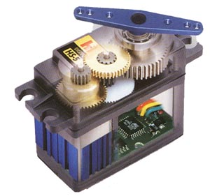
      Information how to solve my second problem I found in the internet. But before that I'll try to explain about the basics of servo performance. Servo has three wires - plus, ground and control. To the plus wire 5V current has to be applied from the scheme that I created in the previous blog post. The fun starts with the control wire. To move servo, pulse signal has to be transmitted. If the pulse signal is 1 ms (approx. 80Hz) the servo will turn fully left, if the signal is 2 ms (approx. 80 Hz) the servo will turn fully right.


Motorized gadget: step #1

     Since I love technical stuff, I have many different ideas in my mind. Mostly they are useless but fun to create, plan and integrate.
     This time I couldn't let go of an idea about motorized panel in my car that would turn 180 degrees when car stereo is switched on. The panel should turn back 180 degrees when car stereo is switched off.  
A lot to do till then, but for now - I'm proud to say that I have finished the first phase!
Since motorization will be done by a servo which uses 5 V current, I encountered my first problem - where to find 5 V in my car?
     My father drew scheme that should convert 12 V to 5 V. With a list of needed components I went to my local radioshack. Few decades ago my father was a radio engineer so many components were already meticulously sorted in small boxes. 

So the scheme: