It's time for the next step. As I mentioned before, I want to create scheme/mechanism that would be able to control servo based on the current in car stereo remote wire (intended to switch on/off audio amplifier).
To understand it better - when I switch on car stereo it gives current on the remote wire, which "says" to the amplifier: "Switch ON!". Scheme "sees" the current in remote wire and starts turning servo to the other end (180 degrees) that flips a panel in center console of the car. When car stereo is switched off, current in remote wire is gone and scheme turns servo the other way around (180 degrees back).
To do this I encountered two main problems:
1. Scheme and servo had to receive 5 V all the time.
2. To control servo it has to receive pulse signal through control wire.
The first problem solving is described in my recent blog post. I created scheme that can reduce voltage from 12 V (which is commonly found in car) to 5 V. The voltage can be adjusted with potentiometer. Scheme works well although, transistor gets very hot. Heat sink will be applied soon to cool it down.
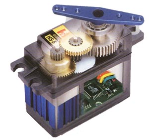
Information how to solve my second problem I found in the internet. But before that I'll try to explain about the basics of servo performance. Servo has three wires - plus, ground and control. To the plus wire 5V current has to be applied from the scheme that I created in the previous blog post. The fun starts with the control wire. To move servo, pulse signal has to be transmitted. If the pulse signal is 1 ms (approx. 80Hz) the servo will turn fully left, if the signal is 2 ms (approx. 80 Hz) the servo will turn fully right.
To achieve this the most important component is NE555 timer and few capacitors that charges precisely 1 and 2 ms. As a template I took the following web site in which this scheme and its performance is perfectly described:http://www.epanorama.net/circuits/servo10v.html
Scheme looks like this:

When I soldered this circuit and integrated it with the previous circuit (previous blog post) I encountered with one problem. This circuit should work by applying 0-10 V current to the "Control Current" input. So based on the voltage servo should change its position - 0 V fully left and 10 V fully right.
Unfortunately this doesn't work as it should be. At this point servo doesn't care about the control current. When I cut the control current input and start to adjust potentiometer, the servo can change its position up to 90 degrees. So this doesn't work as it should be.
For now these are the results:
Soon updates will follow.
Nav komentāru:
Ierakstīt komentāru